Anfragen Call us

Vacuum box testing of welds · Method C3If it bubbles,
it leaks.
Full stop.

Vacuum box testing is a non-destructive method for leak testing welds and geomembranes — classified as method C3 in EN 1779. It is also known as vacuum testing or bubble leak testing. Apply the bubble-forming solution to the weld, place the transparent test box on top, evacuate. If a continuous leak path runs through the weld, air is drawn through it — and the solution reveals the leak as bubbles. You watch it through the Makrolon window. There is nothing to interpret: bubbles or no bubbles.

Section A–A · Vacuum box on a weld READY
Leak path, continuous to pump · NW 7,2 Window (Makrolon) Bubble solution to EN 14291 Boxes per weld type · DN 32 – >1000
LeakingBUBBLES FORMING · TO EN 1593
TightNO BUBBLES · HOLD TIME MET
Hold time: — · 30 s required to DVGW G 469 E3

This rig works: choose the weld condition first, then start the pump.

Key figures Overview · as of 07/2026
POS. 1max. −850 mbarUltimate vacuum, TP seriesStandards require 150–500 mbar
POS. 210⁻⁴–10⁻³ mbar·l/sDetectable leak rateIn practice · ideally down to 10⁻⁵
POS. 36 box typesBoxes, saddles and test framesCircumferential welds · DN 32 to >1000Butt welds · up to 700 mmFillet welds · up to 700 mmExternal cornersInternal cornersCylindrical boxesCustom-built to geometry
POS. 4C3 · EN 1779Classification of the test methodEN 1593 · bubble principleASME BPVC V Art. 10 · vacuum boxASTM E515 · bubble emissionAPI 650 · tank bottomsDVS 2225-2 · geomembranesDVGW G 469 E3 · district heatingEN 14291 · bubble solution
Test procedure

Six steps.
One clear result.How vacuum box testing of a weld actually works

The method is defined in the standards and mechanically simple: a pressure difference between the inside of the component and the evacuated box. A continuous leak path lets air through — and air in the solution is visible. The decisive advantage: the component only has to be accessible from one side. That is why vacuum box testing is the standard method for tank bottoms, bunds and open structures, where a pressure test is not possible at all.

A

Visual check & cleaning

Remove slag, spatter, rust, grease and contamination. Surface at least 5 °C — preheat in frost.

VT to EN ISO 17637 · ≥ 350 lx
B

Check against a reference leak

Test box and pump against a known reference leak first. Only then do you know the set-up will actually show a leak.

Proof of test sensitivity
C

Apply the bubble solution

Wet the whole weld thoroughly. Applying too little is the most common avoidable mistake.

Solution to EN 14291
D

Place the box, evacuate

Place it and press down until the vacuum holds the box by itself. The pump draws the vacuum the standard calls for.

Ultimate vacuum to −850 mbar
E

Watch

Keep to the hold time. Bubbles that stay put and grow are a genuine indication. Bubbles along the gasket are an artefact.

Hold time 5–30 s per standard
F

Mark, retest

Vent, mark the indication with a permanent marker, repair. Move the box on with an overlap and test again.

Overlap ~50–100 mm
Equipment

Pump. Box. Solution.Vacuum leak detectors, test boxes and bubble solution for vacuum box testing

Bubble testing needs nothing more than these three — provided they match. The vacuum boxes are built in-house by AB Industrie Service, designed and made for daily use on site. This page explains the technique; for prices and availability, ask us.

SHEET 01LEAK DETECTORS · TP SERIESOIL-FREE · 230 V

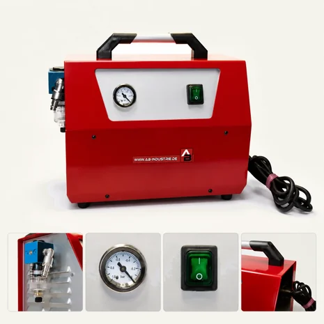
TP 6 & TP 8 vacuum leak detectors

Dry-running rotary vane pump — no oil, no oil mist, little maintenance. NW 7,2 quick coupling for fast box changes on site. The two units differ only in pumping speed — more capacity means large boxes pull down faster.

FigureTP 6TP 8
Pumping speed6 m³/h
= 100 l/min
8 m³/h
= 133 l/min
Ultimate vacuum−850 mbar−850 mbar
CouplingNW 7,2NW 7,2
Voltage230 V230 V
Weight~11,6 kg~11,6 kg
Sound pressure62 dB(A)62 dB(A)
ProtectionIP 54IP 54
TP 6 vacuum leak detector for vacuum box testing of welds, with vacuum gauge, on-off switch and NW 7,2 quick coupling
FIG. 1 · TP-SERIES LEAK DETECTOR WITH COUPLING AND CONTROL DETAILS
SHEET 02BOXES · CIRCUMFERENTIAL WELDS

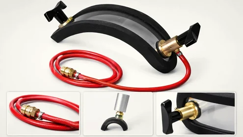
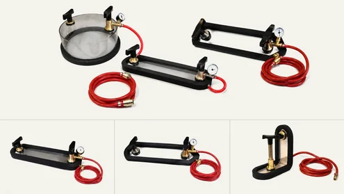
Circumferential-weld boxes DN 32 – >1000

Fixed sizes DN 32–300 and adjustable boxes (DN 125–150 up to >1000) for girth and branch welds on pipe.

Circumferential-weld vacuum box for vacuum box testing of pipe welds, with Makrolon window, contact gasket and NW 7,2 quick coupling
FIG. 2 · CIRCUMFERENTIAL-WELD BOX WITH WINDOW, GASKET AND COUPLING
11 fixed · 5 adjustable sizes Enquire about circumferential boxes
SHEET 03BOXES · BUTT WELDS

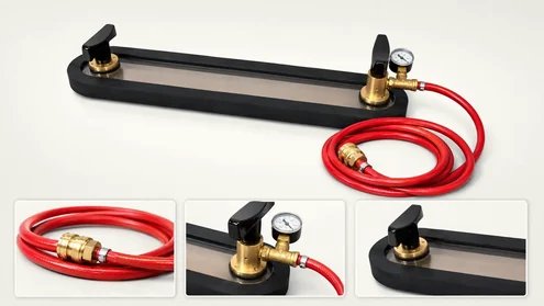
Butt-weld boxes up to 700 mm

Elongated boxes for straight butt welds — tank floor plates, plate joints in vessel work. Test length up to 700 mm per placement; longer welds are covered by moving the box on with an overlap.

Butt-weld vacuum box up to 700 mm for vacuum box testing of straight welds, with long window, contact gasket and shut-off valve; vacuum gauge optional
FIG. 3 · BUTT-WELD BOX WITH WINDOW AND SHUT-OFF VALVE — GAUGE OPTIONAL
for straight welds Enquire about butt-weld boxes
SHEET 04FILLET WELDS

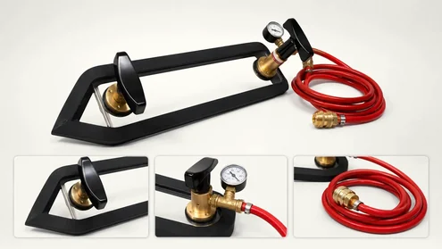
Fillet-weld boxes up to 700 mm

For shell-to-bottom welds and T-joints — wherever two plates meet at an angle. Test length up to 700 mm per placement.

Fillet-weld vacuum box up to 700 mm for vacuum box testing of shell-to-bottom welds and T-joints, with angled contact gasket and shut-off valve; vacuum gauge optional
FIG. 4 · FILLET-WELD BOX WITH ANGLED CONTACT GASKET
SHEET 05SPECIAL SHAPES

Corners, cylinders & custom builds

External and internal corners, cylindrical boxes for branches and pontoon covers. Beyond that we build boxes to your geometry — any fillet-weld angle, welded-in branch penetrations, tight internal corners.

Special vacuum box shapes for vacuum box testing: cylindrical box for branches and pontoon covers, rectangular box and corner box, each with shut-off valve and optional vacuum gauge
FIG. 5 · SPECIAL SHAPES — CYLINDRICAL, RECTANGULAR AND CORNER BOX
built to your geometry Enquire about a custom box
SHEET 06SOLUTION & ACCESSORIES

Bubble solution and connections

The leak detection spray has to meet EN 14291: defined surface tension, foam stability, corrosivity limits. Spray 400 ml (stable down to −15 °C) or concentrate 5 L / 25 L. Plain washing-up liquid does not meet the ASME requirement.

Applying
Pump spray bottle for the concentrate.
Connecting
Vacuum hoses and NW 7,2 couplings.
Measuring
Vacuum gauge 0 to −1 bar — optional, reads the vacuum directly at the box. No gauge can read beyond about −1 bar: that would be absolute vacuum.
Setting
Vacuum regulating valve for the level the standard requires.
Spray, drums & accessories Enquire about the solution
SHEET 07MAINTENANCEWEAR PARTS

Carbon vanes and filters

The dry-running pump needs no oil changes, but it does need cleaning inside from time to time: the carbon vanes shed fine dust. Together with moisture from the solution, that can cause sticking and corrosion.

After every test
Let the pump run on for at least 30 minutes so the moisture is driven out of the pumping chamber. Switching off too early leaves residual moisture inside — it binds the carbon dust and leads to corrosion.
1–2× a year
Open the pump and clean the pumping chamber.
Spare parts
Carbon vanes and filters can be reordered individually — on request.
Not sure what goes together? Tell us the weld type and the dimension — we will put together the matching pump, box and solution.
Box types

Box, saddle,
frame, hood.Vacuum box types by weld configuration

Vacuum box, vacuum saddle, test frame and test hood all work on the same principle and differ only in shape. Depending on the maker, the same tool is called a vacuum test box, bubble test box, leak test frame or simply a vacuum hood. The name matters less than what the contact gasket has to seal around.

TAB. 2 — BOX TYPESBY WELD CONFIGURATION
Box typeApplicationTypical sizes
Circumferential boxpipe girth welds, branches, repair areasDN 32–300 fixed · DN 125 – >1000 adjustable
Butt-weld boxlong straight welds, floor platesup to 700 mm long
Fillet-weld boxshell-to-bottom welds, T-jointsup to 700 mm long
External-corner boxouter corners on vessels and bundsto geometry
Internal-corner boxinner corners, confined areasto geometry
Cylindrical boxbranches, pontoon coversto geometry
Custom buildany fillet angle, branch penetrations, inner cornersto your drawing

Circumferential, butt-weld and fillet-weld boxes are normally 100 mm wide — that is the strip one placement covers. Other widths are built on request.

BUILD & VACUUM SOURCEMATERIALS

Materials

Window
Polycarbonate (Makrolon) — impact-resistant and optically clear. That does not make it unbreakable: check scratched, chipped or aged windows before testing and replace them where needed.
Gasket
Profile rubber as the main seal, plus a soft contact gasket in NBR or EPDM.

Producing the vacuum

Electric pump
Oil-free and dry-running, for continuous duty and large boxes — the TP-series detectors reach −850 mbar. The practical standard, and the only type we supply.
Hand pump
Technically possible, in practice obsolete: by hand you cannot build the vacuum quickly enough for the box to grip and hold itself.
Air ejector
Runs off existing shop air, no moving parts. Rugged on site, but thirsty in continuous use. Not part of our range.

How to identify the right box type

The box follows the weld, not the other way round. Three details are enough to settle the type: the weld configuration — circumferential, straight, fillet, corner or special; the dimension — pipe diameter or weld length; and the seating surface — whether the gasket can sit flat and clean all the way round. Curvature, branches, weld reinforcement and fittings decide whether a standard box will do or a custom build is needed.

Once you have those three, Table 2 points you to the box type. If in doubt, leave it to us — describe the weld.

Standards & detection limits

Tested to standard.
Honest about the limits.Standards and detection limits of vacuum bubble testing

Vacuum level and hold time follow whichever standard applies. And the method only shows what reaches the surface — that belongs to the picture too.

TAB. 1 — TEST PARAMETERSBY STANDARD
StandardVacuumHold timeNote
DVGW G 469 E3200–500 mbar≥ 30 sdistrict heating
DVS 2225-2~300 mbar≥ 10 s~100 mm overlap
ASME Sec. V, Art. 10≥ ~150 mbar5–10 s≥ 50 mm overlap
API 650~200 mbartank bottoms

Under ASME BPVC Section V the hold time is set by the referencing code section — 5–10 s per placement is common practice, not a requirement of the article itself. The classification as method C3 comes from EN 1779:1999; a revision has existed since December 2024 as draft prEN 1779:2024 and is not yet in force.

WHAT IT PROVESSURFACE-CONNECTED ONLY

Detected

  • Through-going porosity & pinholes
  • Cracks running through the wall
  • Root lack of fusion with an opening
  • Pitting & corrosion perforation
  • Leaking branch penetrations & flange gaps
  • Punctures and cuts in geomembranes

Not detected

  • Embedded porosity & cavities
  • Lack of fusion with no opening
  • Sidewall lack of fusion beneath the cap
  • Notch and toughness defects — no strength assessment

Note: not sufficient on its own for pressure components

Safety-related pressure components additionally require volumetric methods — radiography (RT) or ultrasonics (UT). Only those pick up embedded defects and allow a strength assessment. In practice the detectable leak rate is 10⁻⁴ to 10⁻³ mbar·l/s, equivalent to 10⁻⁵ to 10⁻⁴ Pa·m³/s; under ideal conditions 10⁻⁵ mbar·l/s is achievable. That is enough for tank, vessel and membrane work — not for high-vacuum, semiconductor or cryogenic applications.

Is this method right for your job? If you are unsure whether vacuum box testing satisfies your standard, describe the job to us. We will also tell you when another method is the right one.
Documentation

It counts as tested
once it is recorded.Test report and operator qualification for vacuum box testing

Without a report, the test cannot be proven if it is ever disputed. These minimum entries follow EN 1593 clause 10, ASME BPVC Section V Article 10 and DVGW G 469 — which of them is binding depends on the standard that applies to your job.

TEST REPORT — MINIMUM ENTRIES8 FIELDS
  • Client, component and weld identification
  • Equipment: make and model; box by type and size
  • Test vacuum in mbar, hold time in seconds, overlap in mm
  • Bubble solution: designation, batch, manufacturer
  • Surface temperature and illuminance
  • Operator: name and NDT level to EN ISO 9712
  • Result: indications with location, sketch or photograph
  • Date and signatures
QUALIFICATIONEN ISO 9712

Who may carry out the test

Normally a Level 2 leak testing (LT) operator to EN ISO 9712, often combined with visual testing (VT). What governs is the risk assessment and the standard that applies.

Level 1
Carries out the test to written instruction, under supervision. LT training: 5 days.
Level 2
Selects the technique, evaluates results and writes test instructions. LT training: 9 days.
Level 3
Develops procedures and defines the approach.

Certificate valid 5 years · renewed by practical examination

Where it is used

Where it is usedApplications of vacuum box testing, from tank building to landfill

Anywhere the component is accessible from one side only. Besides welds and geomembranes, castings can also be checked for through-going cracks and porosity.

Pos. 01Tank buildingfloor plates · shell-to-bottom weld · API 650
Pos. 02Pipeline workgirth and branch welds
Pos. 03District heatingDVGW G 469, procedure E3
Pos. 04GeomembranesDVS 2225-2
Pos. 05Landfillpolymer liners · BAM · DepV
Pos. 06Potable water tanksDVGW W 300 · KTW
Pos. 07Bunds & containmentWHG · AwSV · StawaR
Pos. 08Flat roofsbuilding waterproofing
Pos. 09Shipbuilding & steelworkalongside MT and UT
Pos. 10Biogas plantsdigesters · membrane connections
Pos. 11Wastewatertreatment basins · pump sumps
Pos. 12Food & pharmastainless steel · CIP/SIP
Pos. 13Castingsthrough-going cracks · porosity
Pos. 14Pressure vesselsAD 2000 HP 5/3 · alongside RT and UT
Pos. 15Floating-roof pontoonsAPI 650, Annex E
Pos. 16Tunnel waterproofingDVS 2225-5
Pos. 17Below-ground waterproofingtanked and integral systems
Pos. 18Process plantflanges · special components
Common questions

Answered briefly.Common questions about vacuum box testing of welds

A detailed technical background article is available in German: Vakuumprüfung von Schweißnähten und Dichtungsbahnen.

F 01What is vacuum box testing of welds?

Vacuum box testing is a non-destructive method for leak testing welds and geomembranes. A bubble-forming solution is applied to the weld, a transparent vacuum box is placed over it and evacuated. Where the weld leaks, the solution reveals it by forming bubbles.

F 02Which standard governs vacuum box testing?

Vacuum box testing is classified as method C3 in EN 1779, and the bubble principle is described in EN 1593. For particular applications, ASME BPVC Section V Article 10 Appendix II, ASTM E515, API 650 for tank bottoms, DVS 2225-2 for geomembranes and DVGW G 469 procedure E3 for district heating apply in addition.

F 03What vacuum level does the test need?

The test vacuum depends on the standard: DVGW G 469 E3 requires 200 to 500 mbar, DVS 2225-2 about 300 mbar and ASME Section V at least around 150 mbar. The TP-series leak detectors reach an ultimate vacuum of −850 mbar and therefore cover every common requirement.

F 04How sensitive is vacuum box testing?

In practice the detectable leak rate is around 10⁻⁴ to 10⁻³ mbar·l/s, equivalent to 10⁻⁵ to 10⁻⁴ Pa·m³/s. Under ideal conditions 10⁻⁵ mbar·l/s is achievable — the same order that ASTM E515 gives as the limit of sensitivity. That is far less sensitive than helium mass spectrometry, but sufficient for tank, vessel and membrane work.

F 05Which defects does the test miss?

Vacuum box testing only finds defects that are open through to the surface. Embedded porosity, cavities and lack of fusion without an opening go undetected. On safety-related pressure components it therefore has to be combined with radiographic or ultrasonic testing.

F 06Vacuum box, saddle, test frame — what is the difference?

Vacuum box, vacuum saddle, bubble test box and leak test frame all describe the same principle in different shapes, and manufacturers often use the terms interchangeably. Flat boxes and test frames cover long straight welds; saddles and shaped boxes sit on girth welds, corners and special geometries.

F 07Which box suits which weld?

For girth welds on pipe there are circumferential boxes from DN 32 to over DN 1000; for straight welds, butt-weld boxes; and for shell-to-bottom welds or T-joints, fillet-weld boxes — both with a test length up to 700 mm per placement. Corner and cylindrical boxes cover internal and external corners as well as branches. All three standard types are normally 100 mm wide. For other geometries AB Industrie Service builds boxes to your drawing.

F 08Which bubble solution is permitted?

The bubble-forming solution has to meet EN 14291, with defined surface tension, foam stability and corrosivity limits. ASME BPVC Section V expressly rules out household soap and washing-up liquid. For polymer geomembranes, DVS 2225-2 does permit soapy water.

F 09Who may carry out a vacuum box test?

Normally a Level 2 leak testing (LT) operator to EN ISO 9712, often combined with visual testing (VT). What governs is the risk assessment and the requirements of whichever standard applies.

F 10Do I need a vacuum gauge on the box?

For most users it is not necessary, because the test vacuum can already be read off the pump's gauge. A gauge on the box is a cost option and shows the vacuum right at the point of test. It is fitted at the works and cannot be retrofitted later.

Advice & quotation

Which box suits your weld?

Weld type, diameter, standard — tell us what you need to test. We will put together the right set of pump, box and solution. Straight answers, no detours.

We use your details solely to answer this enquiry. Required fields are marked *.

Supplier
AB Industrie Service
Frank Abraham
Address
Adolph-Menzel-Strasse 40
04157 Leipzig, Germany
Qualification
Usually Level 2 (LT)
to EN ISO 9712:2022
Ready to test